Retro Z80 computer with CP/M-80
My first computers were home-designed, hand-wired Z80-based CP/M systems. They all used the 8-bit Z80 CPU running at a whopping 4 MHz. That's about 1/4000 the speed of current Intel processors. I built two or three of them before moving on to MS-DOS and eventually Windows computers. The Z80 systems tended to be a bit bulky, sometimes with an entire card just for the low-density dynamic memory.
A few years ago, I thought it would be interesting to build a CP/M system with more modern parts. Memories are much higher density now; the memory for a full 64K (that's kilobytes, not megabytes or gigabytes) fits on one chip. The project doesn't have much practical use unless you want to play old games like Zork. It was just a fun project, like restoring an old car only a lot cheaper.
I toyed with ideas off and on and decided on a system using a Zilog Z80180 CPU. The Z80180 has two built-in serial ports and can access up to 1MB of memory. I used an 8K 28C64 EEPROM to hold the startup code, and I used a HM628128 static RAM to provide 128K of memory. CP/M-80 version 2.2 only supports half of this, but later versions of CP/M support banked memory. The memory is wired so that all 128K can be accessed by the CPU.
Basic specifications for the system are:
Z80180 CPU
128K static ram
32MB SD card for fixed drive storage
Connector for VDrive 3, serial-to-USB for removable storage
Two serial ports, one for console, one for printer, both programmed for 9600 baud
62K CP/M-80 version 2.2
The CP/M operating system has to use low memory, but the Z80 starts at low memory after a reset, which is a problem because the startup EEPROM has to be installed in low memory. I solved this by using the RTS output of the Z80180 to control memory access. The Z80180 has an output bit that is intended to function as a Request To Send for one of the serial ports, but it's controlled by software. So it is effectively a 1-bit output port that initializes in the high state. I connected that bit to the address decoding logic for the EEPROM and RAM. When the bit is high, any read from a location below 0x8000 accesses the EEPROM. Reads and writes above 0x8000 access the RAM. So the EEPROM loads the OS into high memory, then switches control to the OS. One of the first things the BIOS does is reset the RTS bit to zero so all accesses are to RAM, and the EEPROM is disabled.
The system consists of two boards, one for the Z80180 CPU and memory, and the other for an I/O board. The I/O board is controlled by an Atmel (now Microchip) ATMega644 microcontroller. The 644 controls access to a 32GB micro SD card that functions as the system hard drive. For my simple project, I soldered the SD card into the circuit rather than using a socket. The CPU board and I/O board connect using a 26-pin pin-and-socket pair. The CPU board has a 26-pin header on the top with long (wire-wrap) pins on the bottom. The I/O board plugs into the bottom set of pins. The top header is available for additional I/O, although I don't expect to ever use it.
One of the connectors on the I/O board is intended for a VDrive module from FTDIchip. The VDrive accepts a USB flash drive but provides a serial port connection to a microcontroller. It uses simple commands to read and write the flash drive, so it would provide a removable storage mechanism, emulating a floppy drive, but with modern parts.
The choice of an ATMega644 was partly driven by the fact that the Z80180 uses 5V rather than 3.3V. So I needed a microcontroller that could operate at 5V to avoid a lot of 3.3V to 5V interface logic. However, there is some level conversion logic for interfacing to the SD card and the VDrive module.
CP/M can only access about 8MB of storage, so most of the SD card is unused. The Z80180 communicates with the 644 via three registers. When the Z80180 writes to the command register at I/O address 0x40, the 644 reads the register and captures the command. Data is transferred by writing to or reading from address 0x41. A status register at 0x42 lets the Z80 poll the state of the I/O board to see when it can accept new commands or data, and when new data is available to be read.
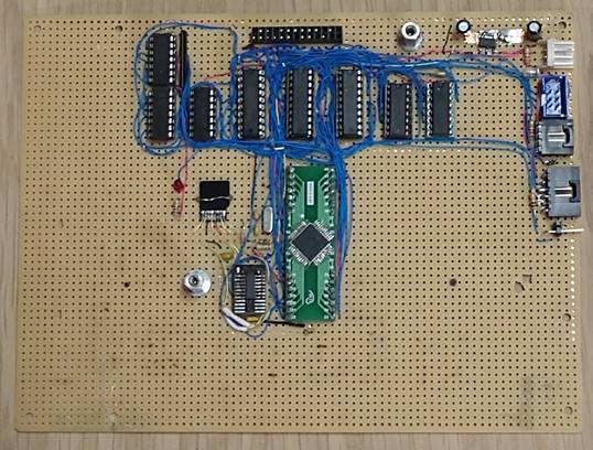
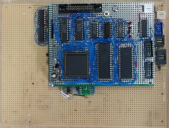
The I/O board is shown below, and the second photo shows the CPU board stacked on the I/O board. There is a lot of space on the I/O board because I may eventually add a video controller so the system can connect to a monitor and a real word processor can be used. Currently, a PC is used as an I/O terminal, running terminal emulation software (PuTTY). You can see that both boards are handwired using wire-wrap wire (but not using wire-wrap sockets). You can see the microSD card to the left of the AVR microcontroller.
I could have put the CPU and I/O on the same board, but I wanted the ability to experiment with different I/O ideas, and I didn't want to have to re-wire the CPU portion every time I did that. As it turned out, I stayed with my first approach.
Bootstrapping the system
One problem with resurrecting an old operating system like CP/M is adapting it to current hardware. Issues include:
CP/M is broken into two parts, the OS consisting of CCP and BDOS, and the machine-specific BIOS. The BIOS is what customizes the operating system to run on the unique hardware. There are many disk images available on the Internet for CP/M that is configured for a specific machine, such as a Kaypro. But unless you have that specific hardware, CP/M won't run. In the old days when CP/M was state of the art, you would write a BIOS that adapts CP/M to your hardware and make a disk for it. But starting from scratch with no existing CP/M system makes it harder.
Floppy disks are completely obsolete. The first CP/M systems I built, long ago, had floppy disk controller ICs that were compatible with the floppy drives used at the time, and CP/M was a floppy-based OS, so the system could be created on the floppy with reasonable ease.
To get CP/M running for the first time, I had to get a CP/M image, with a BIOS for my hardware, installed on the SD card. To make that possible, I did the following:
I found CP/M-80 source code online, and I wrote a simple 8080 assembler in Python to assemble the CP/M-80 source code and my custom BIOS. The assembler creates sector-sized blocks that can be transferred to the SD card via the serial port.
The SD card is configured as 16 sectors per track, which are just how the addressing to the card is managed. Being a floppy-disk-based system, CP/M expects a drive to be defined by tracks and sectors. The EEPROM on the CPU board loads the first 12 sectors into memory. Although CP/M uses only 128-byte sectors, the AVR has modes for loading both 512-byte and 128-byte sectors, so the OS fits on the 16 512-byte sectors of the first track.
The AVR microcontroller includes functions to allow a file to be transferred via the debug serial port and written directly to the SD card, using a simple handshaking mechanism over the serial port.
I built a simple programmer for the EEPROM and used a version of the 8080 assembler to create hex files that can be downloaded to the programmer.
I wrote a serial transfer program in Python to get the hex files to the programmer via the serial port.
Once I had the CP/M OS on the SD card, and had it all working, there was still another problem. The file format used by CP/M is not compatible with current computers. So even if I plugged the SD card into a PC (using an SD to USB adapter of course), copying the utility programs needed by CP/M would be a waste of time because CP/M wouldn't be able to read them.
To solve this problem, I added a unique mode to my BIOS. Normally, when the program in the EEPROM reads the OS and BIOS from the SD card, it immediately executes CP/M. In the special mode, if a jumper on the I/O board is shorted, the BIOS enters a download mode where it accepts hex files via the serial port and copies the binary bytes to the CP/M Transient Program Area (TPA) starting at address 0x100. Only after the file is loaded does the BIOS exit to CP/M.
CP/M has a built-in function named SAVE that allows data in the TPA of memory to be saved to a file. So, for example, the PIP (Peripheral Interchange Program) can be downloaded via the serial port to the TPA area then SAVEd to the SD card. To make this work, I had to write yet another Python program to convert files from binary to the hex format expected by the special BIOS download mode.
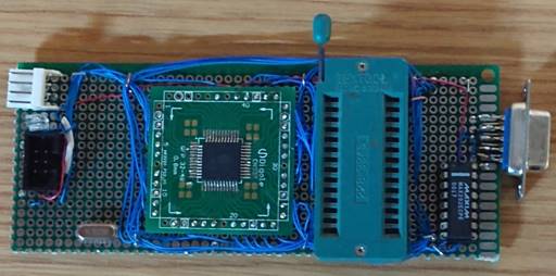
Below is a photograph of the simple EEPROM programmer. The big socket is a ZIF socket for the EEPROM. The programmer uses an ATMega8515 microcontroller and it isn't very sophisticated; it takes advantage of the fact the 28C64 can program either bytes at a time or pages at a time. The programmer just accepts address information and hex bytes, programming them as received. No handshaking. This does limit the serial interface to 9600 baud; any faster and things get lost. I did write another Python program that reads the hex file and then reads the data from the EEPROM and verifies it. The programmer itself is dumb; it can write incoming data to the EEPROM or read the EEPROM and send it as hex-ascii to the host PC, but most of the intelligence is in the PC Python program.
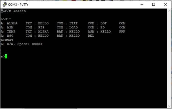
Below is a screenshot of the system after startup. The CPM Loaded message is printed by the EEPROM program after the OS is loaded but before control is transferred to the BIOS. After the a> prompt, I typed DIR to get a directory listing of the files. The HELLO.COM program is a simple assembly-language program that I wrote to make calls into the O/S BDOS to print Hello World just to make sure everything was working. You can see the STAT program reports 8088K (8M) available on the SD card drive. It doesn't seem like much in today's world of 15 terrabyte drives, but it was far more than I ever had on a drive when CP/M was in common usage.
I've been able to edit files using the ED editor (possibly the worst editor ever devised) and assemble them. So the system works and appears to be very stable. I suppose I could download the adventure game Zork and give it a try; haven't attempted that.
What's next
My initial goal of getting everything working was accomplished. I don't expect to switch back to CP/M, as I said, this was just a fun project. But next steps would be the following, in this approximate order:
Get the VDrive working. *** Update 9/29/2019 - VDrive is now working. There was a one-line code bug.
The system communicates with a host only using serial port. As you can see from the screenshot above, I am currently using PuTTY terminal emulation, operating at 9600 baud. I may want to add a video output to the I/O card so as to directly drive a monitor, as mentioned earlier. This would allow the CPU to directly access video memory. An astute engineer would look at the schematics and point out that all the memory is allocated to the RAM. Which is correct, but one of my 80's vintage homebrew CP/M designs used I/O-mapped memory for the video; it worked quite well and wasn't perceptibly slower than memory-mapped video. I would do something similar here. One of the reasons I built this as a 62K system is that I expect the BIOS additions to support video memory will make the BIOS too large for a 64K system. I would still be using the serial port for the keyboard, so I'd have to modify a keyboard (probably with a microcontroller-driven adapter) to have a standalone CP/M system that is independent of a PC. Although this could also be achieved by building a video system that implements a terminal and connecting it via the Z80 serial port. Either way, I would probably drive a monochrome composite video output rather than a VGA output. It has occurred to me that all of the video interface could be implemented with a single TI TM4C1233H6 ARM microcontroller, by using one of the SPI outputs, driven by a DMA channel, as the video dot output and using the timers and the other SPI outputs to generate synchronization and blanking signals.
Make a printed circuit board to replace the hand-wired I/O board. I have created a PCB for the CPU board, but haven't received prototypes yet. I wouldn't bother with a PCB for the I/O board until I add a video interface (or decide not to). *** Update 9/28/2019 - CPU PCB board assembled, picture below.
The current SD card usage isn't very efficient; SD card sectors are 512 bytes but I'm only using 128 bytes of each one (except for the system track). This means that I read and write 512 bytes every time CP/M wants to read or write the SD card, but only transfer 128 bytes to and from the OS. Using the full 512-byte sectors would be more efficient. CP/M has blocking and deblocking capability for mapping the 128-byte OS sectors into larger physical sectors, I just didn't implement it. However, the combination of the solid-state SD card (which has no seek time) and the 10 MHz CPU makes this system run much faster than a floppy-based system, even without that improvement.
Another possible improvement would be to interleave sending read data with the SD reading. Right now, a read command is issued by the Z80, the AVR reads the full 512 bytes of data, and then sends 128 bytes to the Z80, discarding the rest. It would be faster to start sending the 128 bytes to the Z80 as soon as they are read, in parallel with reading the remaining bytes from the SD card. But since another read can't start until the full 512 bytes from the current read or write is completed, it may not improve performance much. I'll have to do the math to determine that before I try to implement it.
Schematics are here:
Picture of CPU PCBA, assembled and working. The PCB is a bit bigger than the handwired board, due to space needed to run traces:

Drop me a line with comments or questions: stuart at stuartball dot com (replace at and dot of course).